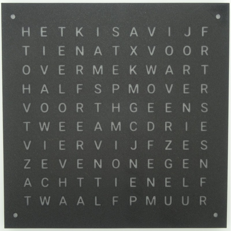
Powered by USB C, can be hung on the wall using holes provided.
Contains an ESP32-C3 and 114 addressable WS2812B LEDs which can show any colour.
You can write your own firmware or simply download the precompiled binary and install it.
Source code available from https://github.com/t0mg/wordclock
Has a battery holder for a CR1632 backup battery which is not included.
Make sure to use a 5V 3A power supply, the clock requires 3A to operate correctly.
Programming
- Visit https://t0mg.github.io/wordclock-flasher/ using Chrome, Edge or another Web Serial compatible browser
- Press the Connect button, a system dialog appears to select a serial interface
- Connect your Wordclock to your computer over USB and a new entry should show up in the dialog. Select that and confirm
- The interface should identify your clock based on the chip it uses (original DIY project, or Nodo kit from nodo-shop.nl) and display a list of available firmware files
- Click FLASH
Alternatively:
- Download the latest firmware_nodo_merged.bin from https://github.com/t0mg/wordclock/releases/
- Plug the USB C cable to your computer and open https://espressif.github.io/esptool-js/ in your web browser (Chrome recommended, see https://caniuse.com/web-serial)
- Click Connect in esptool. Select the correct serial port (on Windows it should be labeled USB Jtag / serial debug).
- The console should then read the information of the ESP and finish with "Changing baudrate to 921600" "Changed".
- Select the firmware_nodo_merged.bin file from your filesystem, change the address field to "0" and press Program.
If this doesn't work you may not have the new bootloader installed, in which case try:
- Remove the 4 back screws to access the PCB.
- Plug the USB C cable to your computer and open https://espressif.github.io/esptool-js/ in your web browser (Chrome recommended, see https://caniuse.com/web-serial)
- Locate the 2 small buttons located in the bottom left corner of the PCB labelled BOOT and RST
- Hold down both, then release RST
- While still holding BOOT:
- Click Connect in esptool. Select the correct serial port (on Windows it should be labeled USB Jtag / serial debug).
- The console should then read the information of the ESP and finish with "Changing baudrate to 921600" "Changed".
- You can release the BOOT button
- Select the firmware_nodo_merged.bin file from your filesystem, change the address field to "0" and press Program.


